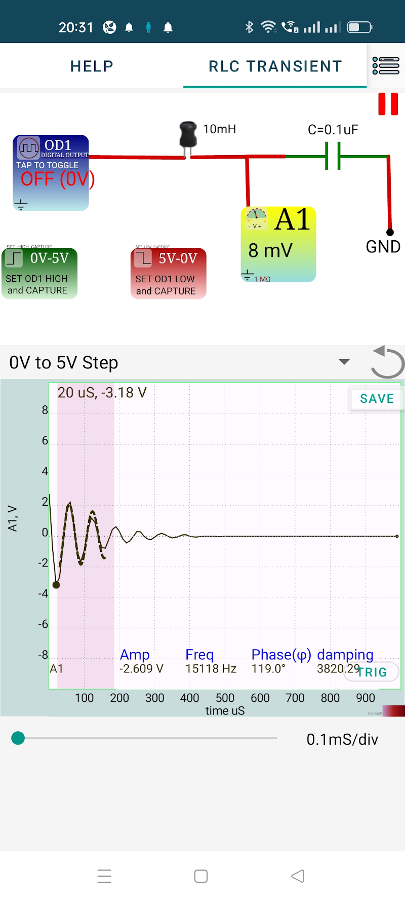
The objecive is to study the evolution of voltage across the capacitor in response to a voltage step applied to the series LCR circuit. Depending on the LCR values, the response can be underdamped, critically damped or overdamped. We have selected the component values:
The circuit schematic and it’s implementation are shown below. The digital output OD1 acts as the battery plus switch. The voltage across the capacitor is captured by the input A1, immediately after applying the volatge step.
From the GUI, the trace can be fitted with a damped sinusoid by selecting a region. The data can be saved/exported, in CSV format.


The experiment may be repeated by connecting ExpEYES to a laptop and using this Python program.
Applying the Kirchoff’s Voltage Law to the circuit gives,
$ L\frac{di(t)}{dt}+Ri(t)+v_c(t)=v_s $
Applying $ i=\frac{dq}{dt}=C\frac{dv_c}{dt} $ to it, and dividing by LC gives
$ \frac{d^2v_c(t)}{dt^2}+\frac{R}{L}\frac{dv_c}{dt}+v_c(t)=\frac{v_s}{LC} $
The characteristic equation of this second order differential equations is
$ \alpha^2+\frac{R}{L}\alpha+\frac{1}{LC}=0 $ whose roots are given by
$ \alpha_1 , \alpha_2=-\frac{R}{2L}\pm\sqrt{(\frac{R}{2L})^2-\frac{1}{LC}} $
Depending on the values of L,C and R there are three types of solutions; under damped, critically damped and overdamped. We are considering the under damped case here.
$ (\frac{R}{2L})^2-\frac{1}{LC} < 0 $
The roots in this case are complex conjugates and can be expressed as
$ \alpha_1=-\frac{R}{2L}+j\sqrt{\frac{1}{LC}-(\frac{R}{2L})^2} =\beta+j\gamma $ ; $ \alpha_2=-\frac{R}{2L}-j\sqrt{\frac{1}{LC}-(\frac{R}{2L})^2} =\beta-j\gamma $
This will lead to a solution $ v(t)=e^{\beta t}K\sin(\gamma t+\theta) $ When t=0, v = 5 volts. This implies $ \theta = \frac{\pi}{2} $.
A damping factor $ \zeta=\frac{R}{2}\sqrt{\frac{C}{L}} $ can be defined.